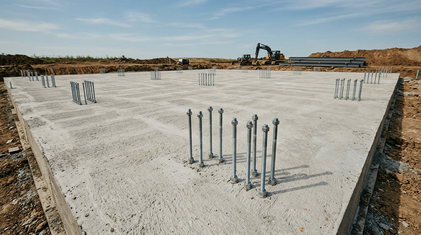
The foundation of a building has one primary job: transfer every pound of dead load, live load, wind uplift, and seismic force safely into the ground without causing the structure to settle, tilt, or pull apart. For a pre-engineered metal building, that job starts long before the first anchor bolt goes in. It starts with knowing what the soil will actually support, what the local code requires, and how the building's column reactions and lateral bracing will interact with the concrete you're about to pour.
Most metal building projects in Florida, Texas, and other high-wind or expansive-soil regions require engineered foundations that meet both the International Building Code and manufacturer-specific anchor-bolt schedules. The slab you see under a finished MBMI structure isn't generic flatwork. It's a designed system, with reinforcement, embedment depths, and edge details calculated to keep the building exactly where you put it for decades.
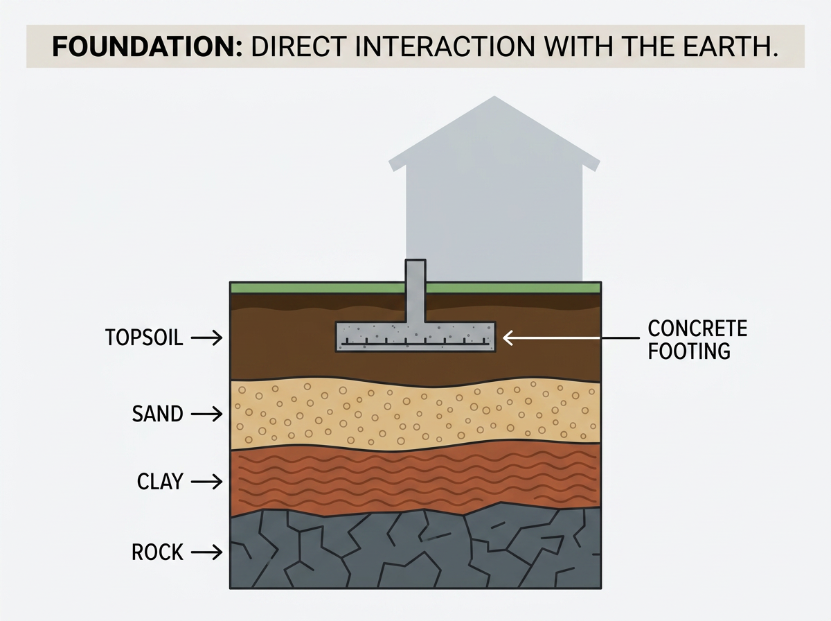
A metal building can be engineered to span 300 feet, resist 180-mph wind, and carry snow loads that would collapse a wood frame. But if the foundation moves, none of that engineering matters. The foundation is the only part of the system that touches the earth, and the earth is never uniform. Soil bearing capacity can vary by an order of magnitude across a single site. Frost heave can lift a footing six inches in a single winter. Expansive clay can swell enough to crack a slab that looked perfect the day it cured.
In our years working with builders and owner-builders across the Southeast and Midwest, the single most common mistake we see is treating the foundation as an afterthought. The building arrives on schedule, the erection crew is booked, and then someone discovers the anchor bolts are in the wrong place or the slab isn't thick enough to develop the required pullout strength. At that point, the fix is expensive and the schedule is blown.
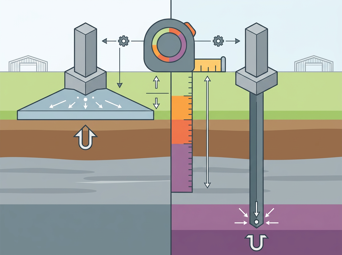
Foundations fall into two broad categories: shallow and deep. Shallow foundations, spread footings, continuous strip footings, mats, and slabs-on-ground, bear on soil or engineered fill within a few feet of the surface. Deep foundations, driven piles and drilled shafts, extend down to competent bearing strata when surface soils won't support the loads.
For most metal building applications, shallow foundations are the default. Ag metal buildings on stable soil typically use isolated column footings or a thickened-edge slab. Commercial structures on good bearing soil can often use a continuous spread footing under perimeter walls and interior columns. Residential steel homes and barndominiums in warm climates frequently use monolithic slab-on-grade systems, where the footing and slab are poured in one continuous pour.
Deep foundations come into play when the site has weak or compressible surface soils, high water tables, or significant flood risk. Coastal Florida projects in FEMA flood zones often require pile foundations that elevate the structure above design flood elevation and resist hydrostatic, hydrodynamic, and wave-impact forces. The Residential Structural Design Guide from HUD describes systems where piles or drilled shafts support grade beams and elevated floor slabs, with specific embedment depths and bracing to resist lateral and uplift forces.
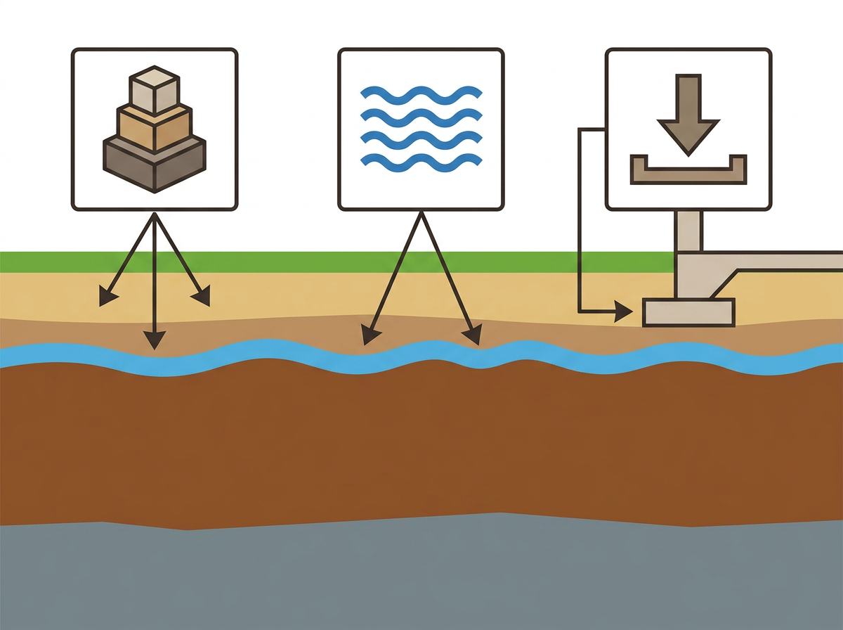
Before you can design a foundation, you need to know what the ground will do. According to the International Building Code, a geotechnical investigation report provides three critical pieces of information: recommended allowable bearing pressure and lateral bearing pressure, results of laboratory testing, and the location and description of the water table, along with recommendations for foundation design including bearing capacity, settlement, and construction considerations.
Most building codes require a geotechnical investigation when site conditions warrant. The investigation typically includes test borings or test pits, laboratory analysis of soil samples, and a written report with recommended bearing pressures and design parameters. For a metal building project, that report becomes the basis for sizing footings, determining embedment depths, and specifying compaction requirements for engineered fill.
If you're working on a site with known expansive soils, common in Texas, Oklahoma, and parts of the Southwest, the geotechnical report will flag the risk and recommend mitigation measures. Expansive soils can cause significant movement and damage if not properly managed. The International Building Code defines expansive soil by plasticity index, particle-size distribution, and expansion potential, and requires that foundations on such soils be designed to minimize damage from volume changes. Common strategies include deeper footings that extend below the active zone, post-tensioned slabs that can tolerate differential movement, or soil treatment to reduce swell potential.
When you're uncertain about subsurface conditions or local code requirements, get in touch with MBMI's engineering team before ordering a soil report. We can help you scope the investigation to answer the questions your building actually needs answered.
A foundation doesn't just sit under the building. It receives specific, calculable forces from every column, every wall panel, and every roof purlin. Those forces include vertical dead and live loads, lateral wind and seismic loads, and uplift from wind suction on the roof. The foundation must resist all of these without exceeding the allowable stresses of the concrete, the soil, or the anchor-bolt embedment.
The American Society of Civil Engineers publishes ASCE 7, the standard for minimum design loads. ASCE 7 defines the load combinations, dead plus live, dead plus wind, dead plus seismic, that the structure and foundation must support. For a pre-engineered metal building, the manufacturer's engineer calculates the column reactions and provides them to the foundation designer. Those reactions become the input for sizing footings, determining reinforcement, and checking punching shear and overturning.
In high-wind regions such as coastal Florida and Texas, building foundations must be designed to resist uplift, overturning, and sliding forces generated by wind loads transferred from the superstructure. According to FEMA's coastal construction guidance, a continuous load path must be provided from roof sheathing through walls to the foundation, and foundations must resist uplift, sliding, and overturning from design wind and flood loads. For institutional steel buildings intended as safe rooms or critical facilities, FEMA P-361 specifies enhanced anchorage criteria to ensure the foundation remains attached to the ground under extreme wind events.
Anchor bolts are the mechanical connection between the building's base plates and the foundation. They must be sized, spaced, and embedded to resist the factored loads from the superstructure, including tension from uplift, shear from lateral loads, and combined tension-shear from wind and seismic events.
Building codes specify minimum anchor-bolt diameters, embedment depths, and spacing. For wood sill plates, the International Residential Code requires minimum 1/2-inch-diameter bolts embedded at least 7 inches into concrete, spaced at a maximum of 6 feet on center and within 12 inches of each plate end. For steel column base plates, the American Institute of Steel Construction provides design guidance for determining bolt size and embedment based on the factored axial load and moment reactions from the column.
In our experience working with erection crews across the country, the most common anchor-bolt issue isn't strength, it's placement. A bolt that's an inch off in one direction might miss the base-plate hole entirely. A bolt that's rotated 15 degrees might interfere with a stiffener plate. That's why MBMI provides detailed anchor-bolt plans with every building package, showing exact coordinates, embedment depths, and projection heights. The foundation contractor uses those plans to set the bolts in a template or jig before the pour, and the erection crew verifies placement before the concrete hardens.
In cold climates, foundation depth is governed by frost. The International Residential Code requires that footings extend below the local frost line to prevent frost heave and resulting structural damage. Frost-line depths vary from a few inches in southern Florida to over 60 inches in northern Minnesota and North Dakota. A footing that doesn't reach below the frost line can be lifted by freezing soil, cracking the foundation and distorting the building frame.
Even in warm climates, drainage and moisture control are critical. Surface water must be graded to direct runoff away from the foundation, with a minimum fall of 6 inches within the first 10 feet. Foundation walls that retain earth and enclose habitable or usable spaces must be waterproofed or damp-proofed to prevent moisture passage. For slab-on-grade foundations, a capillary break, typically 4 inches of clean, coarse aggregate, and a polyethylene vapor retarder beneath the slab help control moisture movement from the ground into the building, reducing risks of mold, flooring damage, and energy loss.
In regions with termite risk, building codes require termite protection at the foundation level. Methods include chemical soil treatment, pressure-preservative treated wood, naturally termite-resistant wood, physical barriers, or combinations of these where the structure meets the ground. The International Residential Code maps termite infestation probability and specifies protection measures for areas classified as "very heavy" risk.
Concrete foundations must meet minimum strength, reinforcement, and detailing requirements to ensure adequate safety and serviceability. According to ACI 318, the Building Code Requirements for Structural Concrete published by the American Concrete Institute, footings must be reinforced in each direction with bars located near the tension face, with minimum reinforcement not less than that required for slabs, and maximum spacing limits to control flexural and temperature-shrinkage cracking.
For a typical isolated column footing under a metal building column, the engineer calculates the required bar size and spacing based on the factored column load, the allowable soil bearing pressure, and the concrete's compressive strength.
Typical concrete strength for building foundations is 3,000 to 4,000 psi, though higher strengths may be specified for heavy loads or aggressive exposure conditions. Reinforcing steel, rebar, is typically Grade 60, with a yield strength of 60,000 psi. The combination of concrete in compression and steel in tension gives the footing the flexural capacity to span across the bearing soil without cracking or failing.
All foundations settle to some degree as the soil beneath them compresses under load. Total settlement is the average vertical movement of the entire foundation. Differential settlement is the difference in settlement between two points, for example, between a corner column and an interior column.
Differential settlement is typically more critical than total settlement. A building that settles uniformly by an inch might experience no structural distress. A building where one corner settles an inch and the opposite corner settles a quarter-inch will see distortion of the frame, binding doors and windows, and potential cracking of cladding and interior finishes.
Foundation design must consider both immediate settlement (which occurs as the load is applied) and long-term consolidation settlement (which occurs over months or years as water is squeezed out of compressible soil layers). The geotechnical engineer predicts settlement based on soil properties and load magnitude, and the structural engineer checks that predicted settlements do not exceed tolerable limits for the specific building type.
For many metal building applications, especially in warm climates where frost depth is not an issue, a slab-on-grade foundation is the most economical choice. The slab serves as both the foundation and the floor, eliminating the need for separate footings and a structural floor system.
A monolithic slab-on-grade pours the footing and slab in one continuous operation. The perimeter of the slab is thickened and deepened to act as a footing, and the interior slab is typically 4 to 6 inches thick with welded-wire reinforcement or rebar. The slab is supported on a prepared subgrade, usually 4 inches of compacted granular fill, over undisturbed or engineered soil.
A floating slab is similar but not structurally connected to perimeter grade beams or footings. It's used where differential movement is expected and the slab is allowed to move independently of the perimeter foundation.
Post-tensioned slabs are designed with high-strength steel tendons embedded in the concrete. After the concrete reaches a specified strength, the tendons are tensioned, placing the slab in compression. According to the Post-Tensioning Institute, this improves crack control and allows the slab to better span over localized soft spots or volume changes in expansive soils. Post-tensioned slabs are common in Texas, Oklahoma, and other regions with expansive clay soils.
For agricultural buildings, riding arenas, and some residential applications, pole-frame or post-frame construction offers an economical alternative to conventional steel-frame systems. In post-frame construction, the vertical columns, either pressure-treated wood posts or concrete piers, are embedded directly in the ground, and the roof and wall framing is attached to those columns.
According to the National Frame Building Association's design manual, post-frame foundations consist of embedded posts or piers designed for axial, lateral, and moment loads from the superstructure and wind. Embedment depth must be sufficient to develop required lateral resistance and extend below frost depth or be protected against frost heave. Typical embedment depths range from 4 to 6 feet, depending on soil type, frost depth, and lateral load magnitude.
Every metal building project is unique. Soil conditions vary. Wind and snow loads vary. Occupancy classifications and code requirements vary. That's why MBMI includes in-house engineering support with every project. Our engineers review the geotechnical report, calculate the foundation loads, and provide stamped foundation drawings and anchor-bolt plans that meet local code requirements and the building manufacturer's specifications.
When you request a steel building quote, you're not just getting a price for steel and panels. You're getting a complete engineered system, with foundation recommendations, anchor-bolt schedules, and erection drawings that ensure the building goes together correctly the first time. That's the difference between a kit and a solution.
The foundation is the part of the project you'll never see once the building is up. But it's the part that determines whether the building will still be square, plumb, and weathertight twenty years from now. Get it right the first time.
Further reading: 2018 International Building Code (IBC), Chapter 18 Soils and Foundations.